Bend Radius For Sheet Metal
So, I was wrestling with this piece of aluminum the other day, trying to bend it into a somewhat reasonable shape for a DIY project – you know, one of those things where you think it'll be easy, and then the metal laughs in your face. I was aiming for a nice, tight curve, the kind you see on fancy motorcycle fenders. I cranked on the bending brake, thinking, "This is going to be epic!"
Next thing I know, there's this horrible ping sound, followed by a distinct crackling noise. My beautiful, intended curve? It was more like a sad, jagged scar. And the edges? Oh, the edges were not happy. They looked like they’d been chewed by a grumpy badger. Lesson learned, my friends. And that, my dear readers, is where we dive headfirst into the wonderfully complex, surprisingly crucial world of bend radius for sheet metal.
It sounds super technical, right? Bend radius. Like something an engineer would mutter over a CAD drawing. But honestly, it’s one of those things that can make or break your project, whether you’re building a spaceship (okay, maybe a little ambitious for a DIYer, but you get the idea) or just a simple bracket for your workshop. And if you don’t get it right, well, you might end up with something that looks less like a finished product and more like… well, like my aluminum disaster.
What Exactly Is Bend Radius, Anyway?
Let’s break it down, shall we? Imagine you’re taking a piece of paper and you want to fold it. The bend radius is basically the inner radius of that fold. In the world of sheet metal, it’s the radius of the inside curve where the metal bends.
Think of it like this: if you were to trace the center of the bend, that imaginary line would form a circle. The radius of that circle, measured from the center to the metal, is your bend radius. Simple enough, when you put it like that, isn’t it? It’s the difference between a sharp, crisp ninety-degree angle (which, spoiler alert, is usually a bad idea for most metals) and a nice, smooth transition.
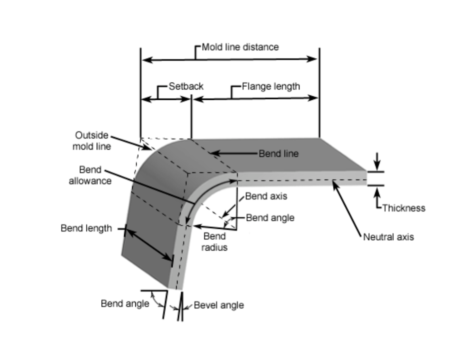
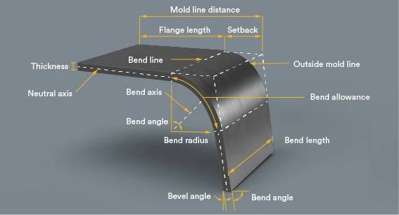
There are a few key terms that pop up here, and it’s good to get them straight. You’ll hear about the inside bend radius (the tightest curve on the inside), the outside bend radius (the curve on the outside, which is larger), and the bend tangent line (the imaginary lines that define where the bend starts and ends).
And then there’s the K-factor. Oh, the K-factor. Don’t let the name scare you. It’s essentially a ratio that describes where the neutral axis (the imaginary line within the material that doesn’t stretch or compress during bending) lies during the bending process. It’s super important for calculating bend allowances, which we’ll get to later, but for now, just know it’s a thing, and it’s a bit of a… well, a variable thing.
Why Should I Care About This Bend Radius Thingy?
Okay, so why all the fuss? Can’t I just bend it how I want? Well, you can, but it might not turn out the way you’d hoped, or worse, it might fail spectacularly. And nobody wants a spectacular failure, right? Unless you’re aiming for internet fame, which, let’s be honest, is a whole other ball game.
Here’s the lowdown on why bend radius is your new best friend (or mortal enemy, if ignored):
- Material Integrity: When you bend metal, the material on the outside of the bend is being stretched, and the material on the inside is being compressed. If you try to bend it too sharply (i.e., with a radius that’s too small), you can exceed the material’s ability to stretch. This is what happened to my poor aluminum. It fractured. Cracking, tearing, and even wrinkling on the inside are all potential consequences of a too-tight bend.
- Dimensional Accuracy: The bend radius directly affects the final dimensions of your part. If you don’t account for it, your part won’t be the size you expect. This is particularly crucial in precision applications where even a millimeter can make a difference. Think about fitting two pieces together – if one is slightly off because of an ignored bend radius, they might not mate correctly. Frustrating, to say the least.
- Tooling Life: Bending metal puts stress on your tooling – your press brake dies, your punches, even your hand tools. If you consistently try to achieve radii that are too small for the material and tooling combination, you’ll wear out your tools faster. And nobody likes buying new tools, am I right? It’s an investment!
- Aesthetics: Let’s be honest, sometimes you just want things to look good. A sharp, ragged bend just doesn't have the same elegance as a smooth, consistent curve. The bend radius plays a huge role in the visual appeal of your finished product.
So, there you have it. It’s not just a number; it’s a key player in the metal-bending drama.
The “Minimum Bend Radius” – Your New Mantra
This is where things get really interesting. Every type of sheet metal has a minimum bend radius it can handle without suffering damage. This minimum radius is influenced by a bunch of factors, and it’s not a one-size-fits-all kind of deal.
What dictates this magical number? Well, several things:
- Material Type: This is probably the biggest factor. Softer metals like aluminum and copper can typically be bent to tighter radii than harder metals like stainless steel or high-carbon steel. Think about bending a piece of butter versus bending a piece of steel – same concept, different materials!
- Material Thickness: Thicker material requires a larger bend radius. Trying to bend a thick plate to the same tight radius as a thin sheet is a recipe for disaster. It’s like trying to bend a pencil versus trying to bend a broomstick.
- Temper/Hardness: Even within the same material type, different tempers (or degrees of hardness) will have different minimum bend radii. A soft temper will bend easier and to a tighter radius than a hard temper of the same metal.
- Grain Direction: This one is a bit more advanced, but for some critical applications, the grain direction of the metal can influence how it bends. Generally, it's best to bend across the grain, if possible, for tighter radii.
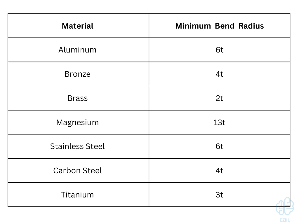
So, how do you find this elusive minimum bend radius? You don’t just guess. You look it up! Manufacturers and material suppliers provide this information. It’s usually found in technical data sheets or material specifications. If you’re buying from a reputable supplier, they should be able to point you in the right direction. Or, you might find handy charts online (just make sure they’re from a reliable source!).
A common rule of thumb you might see is a multiplier of the material thickness. For example, a certain alloy might have a minimum bend radius of 1 times its thickness (1T), meaning if you have 1mm thick material, the absolute smallest radius you should aim for is 1mm. Others might be 2T, 3T, or even more. It’s crucial to respect these numbers.
The Art of Calculating Bend Allowance
Now, this is where we move from just avoiding disaster to actually designing with intent. If you need your part to have specific dimensions after bending, you can’t just measure the flat piece and expect the bent piece to be the same. Why? Because of that stretching and compressing we talked about earlier. The material effectively gets longer on the outside of the bend and shorter on the inside.
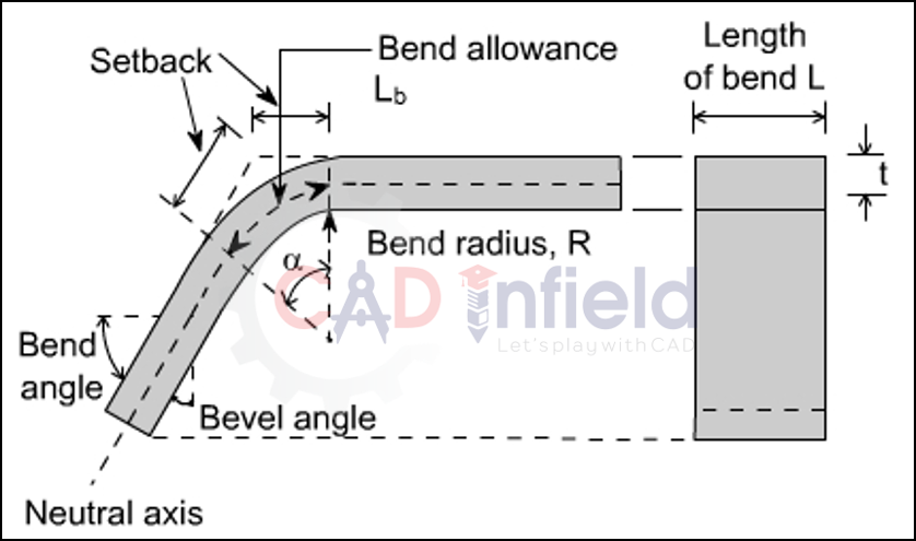
This is where bend allowance (BA) comes into play. Bend allowance is the length of material that is actually being bent. It’s the amount you need to add to your flat layout dimension to account for the material that forms the curve.
Calculating BA involves a bit of geometry and those K-factor concepts we touched upon earlier. The basic idea is to calculate the arc length of the bend. The formula often looks something like this:
BA = (2 * π * R) * (θ / 360)
Where:
Ris your outside bend radiusπis pi (approximately 3.14159)θis the bend angle in degrees
However, this formula assumes the neutral axis is exactly in the center of the material, which, as we know, isn’t always true due to the K-factor. Different K-factors will shift the neutral axis, affecting the actual length of the bent section. There are more advanced formulas that incorporate the K-factor (often ranging from 0.3 to 0.5 depending on the material and bend conditions) for more precise calculations. You might see formulas like:
BA = (2 * π * (R + K * T)) * (θ / 360)
Where T is the material thickness, and K is your K-factor. Pretty neat, huh?
Alternatively, and often more practically, engineers and designers use bend deduction (BD). This is the amount by which the flange lengths are reduced due to the bend. It’s essentially the sum of the lengths of the two tangent lines minus the length of the neutral axis.
BD = 2 * (R + T) * tan(θ/2) - (2 * π * (R + K * T)) * (θ / 360)
This can get a bit heavy on the math side, so don’t worry if it makes your eyes glaze over. The good news is that most CAD software and even many online calculators can do these calculations for you. You just need to input your material type, thickness, bend angle, and desired inside bend radius, and it’ll spit out the bend allowance or bend deduction. Game changer!
Choosing Your Bend Radius Wisely
So, you know the minimum, you know the math (sort of). How do you actually choose the bend radius for your project? It’s a balance of several things.
Start with your material and its thickness. This gives you your absolute floor for the minimum radius. Don’t even think about going below it.
Then, consider your tooling. If you’re using a specific punch and die set on a press brake, the available radii of those dies will influence your choices. Sometimes, you’re limited by what you have on hand.
Next, think about the strength requirements of your part. A larger bend radius generally results in a weaker bend compared to a tighter radius (all else being equal, and this is a simplification!). If you need a very strong corner, a slightly tighter radius might be beneficial, as long as it’s still within the material’s capabilities.
And of course, the functional and aesthetic requirements of your design. Does the curve need to fit a specific contour? Does it need to look a certain way? These are often the primary drivers.
A common practice in design is to select a bend radius that is at least 1.5 to 2 times the material thickness. This provides a good safety margin, reduces the risk of cracking, and often results in a cleaner bend. But again, always check your material specifications!

The “Crunch” Factor: What Happens When It Goes Wrong
We’ve talked about cracking, but let’s delve a little deeper into the symphony of errors that can occur when you ignore bend radius.
On the inside of the bend, where the material is compressed, you can get wrinkles or buckling. Imagine scrunching up a piece of paper; it doesn’t stay smooth. The metal does something similar when it’s forced into too tight a curve. These wrinkles can weaken the part and look pretty unprofessional.
On the outside, we’ve already mentioned cracking. This is usually due to the material being stretched beyond its elastic limit and then fracturing. Once that happens, the part is compromised, and often, it’s irreparable. Cue the sigh and the need for a new piece of metal.
There’s also the issue of springback. When you release the bending pressure, the metal will try to spring back to its original, flatter shape. The amount of springback is influenced by the material, its temper, the bend radius, and the tooling used. A tighter bend radius generally results in less springback, but it also increases the risk of cracking. So, it’s a balancing act. You often have to overbend slightly to compensate for springback, and this is where understanding bend allowance and using the right tooling comes in handy.
A Final Word of Caution (and Encouragement!)
Look, I know this can seem like a lot. But the truth is, the more you work with sheet metal, the more intuitive these things become. You’ll start to develop a feel for what a particular metal can handle. But when in doubt, always, always consult the data sheets. They are your golden ticket to a successful bend.
Don’t be afraid to experiment, either. Start with scrap pieces. Try bending at different radii and see what happens. Make notes. Learn from your mistakes (and my mistakes, for that matter!). That horrible ping I heard? It was a valuable, albeit slightly painful, learning experience.
So, the next time you’re faced with bending a piece of metal, take a moment. Think about that bend radius. It’s more than just a number; it’s the key to a strong, accurate, and beautiful piece of work. And who doesn’t want that?